Micro-scale Impact testing – a new approach to studying fatigue resistance
Increasing the sensitivity of the impact test
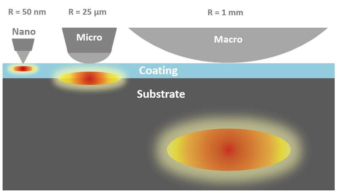
Changing the applied load and probe geometry in an impact test, alters the severity of the test and to move the positions of peak impact-induced stresses relative to the coating-substrate interface, so the test can be sensitive to differences in adhesion and the presence of weak interfaces in multilayer coatings (Figure 1)
Figure 1 influence of probe geometry on location of peak stresses
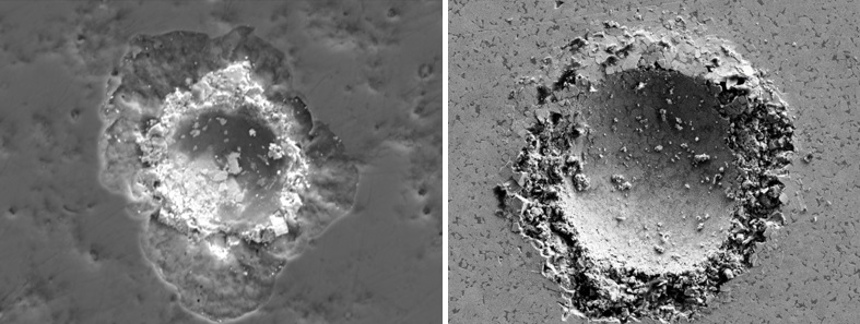
The maximum energy supplied per impact with the Micro-Impact technique is around 2 orders of magnitude greater than the maximum possible in nano-impact resulting in significant damage within a short test time (Figure 2).
Figure 2 Failure of TiAlSiN coating and WC-Co
Overcoming limitations of macro-scale impact
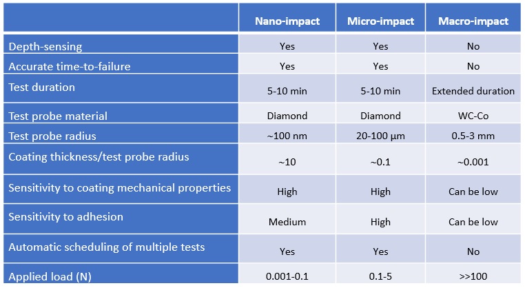
Although traditional macro-scale repetitive impact tests are simple they have some drawbacks that can limit their usefulness. Key differences between the macroscale approach and the fully instrumented micro and nano-impact tests developed at Micro Materials are shown in the table below:
The Micro-Impact test technique can be used for:
Fatigue resistance studies
Fracture mechanisms
Simple time to failure studies
Nano- to micro load range
Optimise and improve your coatings
Optimise max. stress position
Bulk or coated sample
Test procedure
Acceleration of the probe to the sample surface creates the impact. The impact energy and effective impact force are controlled by varying the static load and the accelerating distance. The micro-impact tests were performed with an accelerating distance of 40 microns from the initial surface and the applied load varied in the range 0.5-3 N. The test duration was 300 or 600 s with 1 impact every 4 s. A sphero-conical diamond with end radius 20 µm was used.
Case Studies
Optimising DLC film architecture for crack resistance
A major barrier to the greater adoption of low friction DLC coatings in more demanding applications is their low resistance to contact damage. Despite being hard and elastic and performing very well at low loads, typically they behave poorly at higher load. They are susceptible to abrupt increases in wear rate as the load increases beyond a critical threshold [1].
Optimising their resistance to crack initiation and crack propagation (damage tolerance) has therefore become an important research area. Common strategies to improve the resistance to contact damage include deposition of adhesion promoting interlayers, multilayering, changing sp3/sp2 through bias control, gradient layers, metal doping and deposition of load-supporting sub-layers. The micro-impact test provides a quick and efficient method to evaluate new coatings designs.
Figure 3 Load dependence of the final impact depth for various multilayer DLC coating systems on hardened tool steel
Figure 3 shows the load dependence of the impact depth at the end of the micro-impact test on 4 different types of multi-layered PVD DLC coatings on hardened steel substrate. In this example the a-C:H (the hardest film with highest H/E and H3/E2) behaves poorly, with the Si-doped DLC being even worse. The other two coating systems were significantly more impact resistant despite being slightly softer.
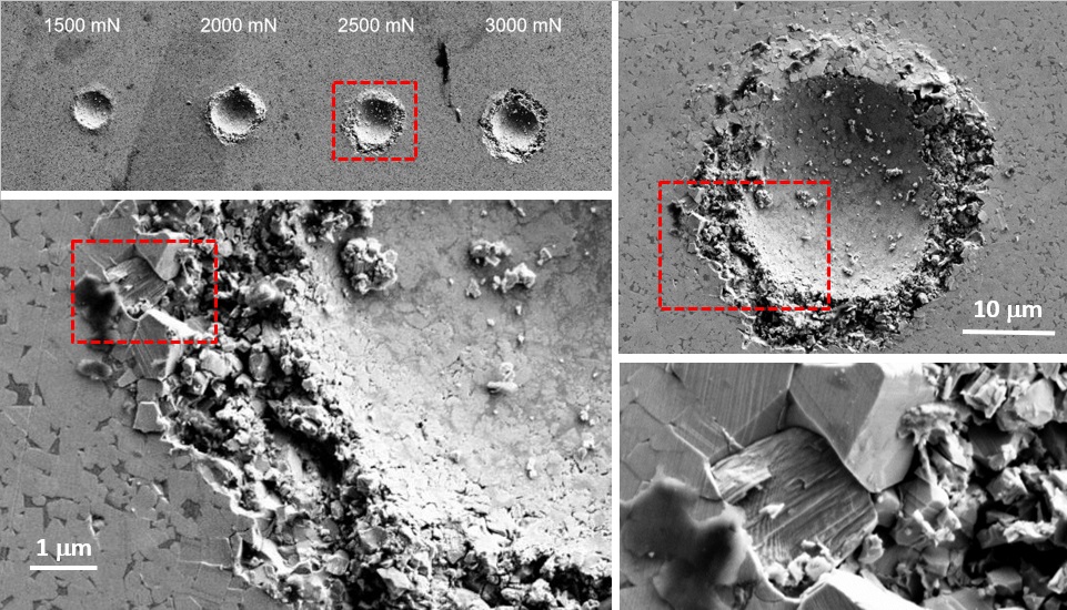
Differences were confirmed by microscopic analysis of the impact craters, as illustrated in Figure 4. At 0.5 N the a-C:H system fails in 3/5 of the 300 s tests and all of the higher load tests. The failure was not observed on the a-C:H:W multilayer.
Figure 4 Optical micrographs of impact grids on a-C:H (left) and a-C:H:W (right).
The Micro-Impact test provides an accurate measure of the time and number of cycles to failure so it is possible to produce an S-N curve. Figure 5 shows a typical example for three coatings that show low crack resistance. There are clear differences in time-to-failure with the graded a-C:H deposited by unbalanced magnetron sputtering being more resistant.
Figure 5 Time to failure vs. applied load for multilayer DLC coatings on hardened steel
Improving wear resistance of hard metals
Hard metals such as cemented carbides combine high hardness with high fracture toughness which can result in excellent wear resistance in highly loaded contacts. In determining which grade to use the fracture toughness or hardness alone may not be the best indicator of performance in the application. In the example below two grades of WC-Co were subjected to micro-impact tests at 1.5-3 N
Figure 6 Comparative impact performance at 3 N for cemented carbide with 4.8% Co binder (red) and 6.0% Co (blue).
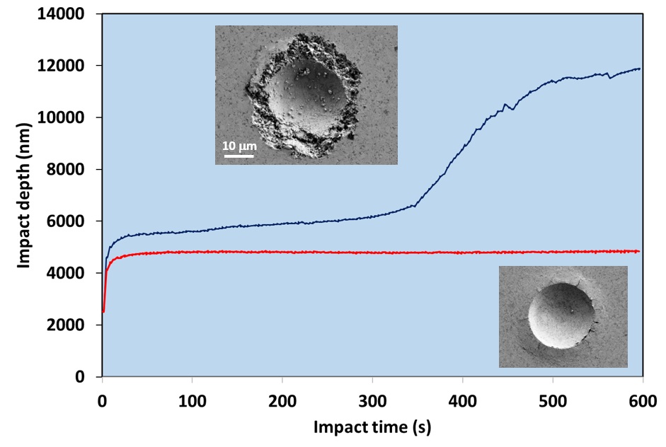
The WC-Co grade with lower % Co binder and lower Palmqvist fracture toughness displayed improved damage tolerance in the Micro-Impact test with some radial cracking at the highest load (Figure 6). However, the grade with higher binder was susceptible to more severe degradation on repetitive contact, even at the lowest load tested of 1.5 N. SEM images of a typical 2.5 N repetitive impact test on the sample with 6.0 % Co are shown in Figure 7.
The differences cannot only be explained by the difference of binder content; in the grade with lower % binder, the presence of cubic carbides inhibit the grain growth leading to different plastic deformation mechanisms.
Figure 7 typical 2.5 N repetitive impact test on the sample with 6.0 % Co.
Simulating high speed machining
The Al-rich nitride coatings AlTiN and TiAlCrN have very similar hardness (H»26 GPa) but their performance in high speed cutting tests of hard-to-cut aerospace alloys (Ni-base superalloy Waspaloy, and Ti-based alloys such as Ti6Al4V) is different [2-4]. Micro-Impact tests were used to simulate the cutting tests [5].
Figure 8 Evolution of impact depth with time for micro-impact tests at 1.25 and 1.75 N on AlTiN and TiAlCrN coatings on WC-Co.
Figure 8 shows Micro-Impact tests at 1.25 and 1.75 N. Initial impact resistance at 1.25 N is similar but with continued impacts the impact depth on TiAlCrN increases due to fracture starting at 40 s. Both coatings fail at the higher load but failure occurs rapidly on TiAlCrN whilst the time to failure is much longer on AlTiN. Typical tool life data in machining aerospace alloys are illustrated in the inset for end milling of Ti6Al4V.
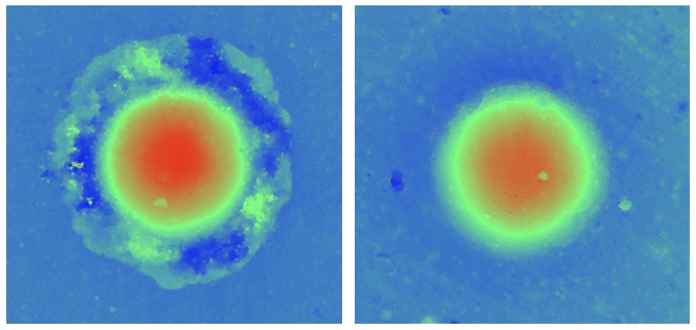
The repetitive contact in the milling test is effectively simulated in the micro-impact test and the AlTiN displays significantly higher fracture resistance than the TiAlCrN in both tests. The rapid Micro-Impact test can be effective in developing new coatings for these applications. The failure occurs at the periphery of the impact crater where the tensile stresses are greatest as illustrated for TiAlCrN in Figure 9.
Figure 9 Confocal microscopy images of (a) failure on TiAlCrN (b) AlTiN
Conclusions
The repetitive contact impact test reveals differences not observed on initial impact. In many cases damage tolerance under repetitive contact requires an optimum combination of hardness and toughness and since it is generally not possible to predict performance from quasi-static tests a direct approach has distinct benefits.
Results from the quick and simple Micro-Impact test have shown a very high level of correlation with actual performance in erosion, metal cutting and other severe applications for coatings and hard metals.
In this complex area the new micro-impact technique is proving a valuable addition to the range of laboratory characterisation tools, reliably screening potential promising coatings systems on the basis of their resistance to fracture on repetitive contact and highlighting potential weaknesses in others (low fracture resistance, weak interfaces…). It can streamline the coating development process, enabling savings in time and money.
Benefits of assessing fatigue resistance with the Micro-Impact test
Very short duration of the experiments compared to conventional tests allowing rapid screening to evaluate the performance of novel coating compositions
multiple rapid tests possible on single samples
possibility to schedule experiments on multiple samples for rapid performance comparison
flexibility to alter loading level and severity of impact loading
accurate recording of cycles to failure
information on the fatigue failure mechanism
combine with other NanoTest techniques (e.g. nanoindentation, nano-scratch) to build up a more complete picture
Acknowledgements and References
MML would like to thank Innovate UK and our collaborative partners (Cranfield University and Thin Metal Films) on the project #132369 – Nano-to Micro-Impact Testing: An in-situ test for UK SEAC sector, together with many others who have helped with developing the new technique including Dr Núria Cinca (Hyperion) and Dr Tomasz Liskiewicz (University of Leeds).
GS Fox-Rabinovich et al, Surf Coat Technol 204 (2009) 489.
B.D. Beake et al, Wear 418-419 (2019) 102.
J. Chen et al, Surf Coat Technol 206 (2012) 4992
Also check out our new high temperature micro-scratch and impact testing tech note which describes case studies that combine the proven NanoTest high temperature capability with micro-scale scratch and impact tests on hard, wear-resistant coatings.