Imaging & Positioning
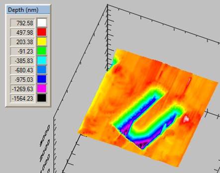
2D and 3D Imaging


Images taken on wood cells using the four lenses on the multiple objective microscope. Images can then be used to position indent sites.
Images taken on wood cells using the multiple objective microscope. Images can then be used to accurately position indent sites.

In order to target/avoid specific structures or features on samples, all NanoTest systems are equipped with multiple-objective optical microscope. The optical microscope is also useful for reviewing residual damage post-experiment.

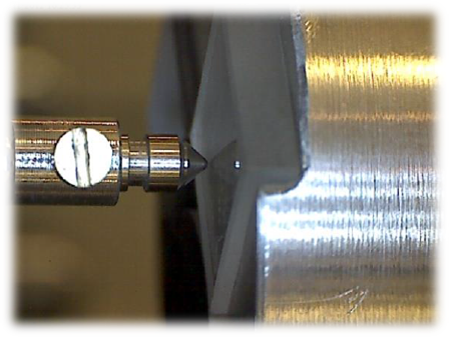
In addition to the multiple-objective microscope, a side-view optics microscope is supplied with the system to provide the convenience of a close-up view of the indenter and sample.

The NanoTest systems can also be configured with additional imaging capabilities including high temperature optics, an in-situ 3D nanopositioning stage, and an AFM.

How it works

The sample stage features five measurement positions as shown below. All of these capabilities are optional, as the NanoTest systems can be configured to meet the requirements of the customer.

  • 1: High temperature opticsresizedimage259124-imaging-fig01
  • 2: Low Load Head
  • 3: AFM
  • 4: High Load Head
  • 5: Multiple Objective Microscope

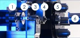
The sample (6) automatically moves between the loading heads and the imaging devices via software control. The high accuracy stages used by the NanoTest systems provides a resolution of 20 nm and a re-positioning accuracy of < 400 nm.

Standard Optics on the NanoTest Vantage

The NanoTest is supplied with a multiple-objective microscope, and side-view optics as standard. The multiple objective microscope has two lenses mounted in a precision shuttle mechanism for accurate re-positioning. Lenses are selected using software control. The two lenses, as well as 2x digital zoom allows wide and precise positioning on samples, and the ‘point-and-click’ functionality ensures quick and easily movement.

Indents on a cast iron sample. Indents were precisely placed using the optical microscope in order to avoid the ferrite/perlite structures seen on the sample.
The view from the side-view optics, which allows visualisation of indenter-sample contact.

Additional Options

In-Situ Profiler and Nanopostioning Stage

The 3D profiler stage allows three-dimensional images to be created in-situ. A piezo-driven stage behind the sample moves the sample across the probe, building up a 3D image.

This also doubles as a nanopositioning stage, giving a sample re-positioning accuracy of up to 3 nm. This very high resolution and re-positioning accuracy means features too small to targeted with the optical microscope can be targeted with the nanopositioner. The maximum scan range is 100 µm x 100 µm.

resizedimage268265-imaging-fig06

resizedimage298265-imaging-fig07

Imaging at high temperature

Nanopositioner image of a micro-cantilever at 700 ºC. (Data courtesy of DEJ Armstrong, J Gibson and SJ Roberts, University of Oxford)

The Nanopositioning stage can be used to produce 3D images of the sample across the entire operating temperature range of the NanoTest Vantage and NanoTest Xtreme. This means that features too small to be targeted with the optical microscope can easily be targeted, even at high temperatures.


Atomic Force Microscope

A dedicated AFM can be integrated onto the NanoTest Vantage to provide AFM-resolution images of experiment test sites. The AFM comes supplied with a complete software suite for image analysis.

Maximum scan range 110 µm x 110 µm.

Find more information about the integrated AFM on the Nanosurf website below:

https://www.nanosurf.com/en/products/naniteafm-afm-for-large-samples

resizedimage241145-imaging-fig08

resizedimage200148-imaging-fig09